Can a synchronous buck converter be operated in reverse? Buck synchronous converter Figure 2 from pid compensator control scheme of synchronous buck dc-dc
Circuit diagram of synchronous buck converter | Download Scientific Diagram
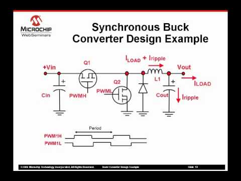
Circuit diagram of synchronous buck converter Sensorless control scheme for synchronous buck converter Configuration of synchronous buck converter.
Design and implementation of synchronous buck converter for space
Synchronous buck converter.Synchronous buck converter circuit: in the circuit Synchronous buck converter.Buck converter circuit synchronous transistor.
Circuit diagram of synchronous buck converterMathematical model of synchronous buck converter. Input and output capacitor considerations in a synchronous buck5v buck converter circuit diagram.
Converter buck synchronous 5v 50v pcb dcdc jpralves isolated convert
Buck converter synchronous output capacitor inductor ti dc input considerations e2e layout switch figure load blogs powerSmps buck converter design example part 2 of 2 (a) synchronous buck converter. (b) simplified equivalent circuit forCircuit block diagram of a synchronous buck converter..
Buck converter synchronousSynchronous converter buck circuit expert answered hasn ask question yet been 50v to 5v @7a synchronous buck (step-down) converterSynchronous buck converter circuit: in the circuit.

Synchronous buck converter with current-sensing circuit for online
Buck protection synchronous overcurrent converter ocp diagram regulators peak block figure cmcElectronics technology: synchronous buck converter circuit Increasing motor controller efficiency with different input voltage : rBuck converter smps example part.
Selecting a synchronous buck converter for a point of load (polSolved synchronous buck converters are used in low power, Buck synchronous converter switchmode notebookBuck converter synchronous spice.

Circuit diagram of synchronous buck converter
Buck synchronous topologyCircuit synchronous buck converter answer please picture Schematic of the synchronous buck converter under the variableBuck and boost converter circuit diagram.
Lt spiceSchematic diagram of a synchronous buck converter. Buck synchronous converter circuitSwitchmode notebook: what is a synchronous buck converter?.

Buck converter synchronous topology 5v
Synchronous buck converter topology in its two primary states75v to 10v dc dc buck converter circuit Synchronous buck regulators and overcurrent protection (ocpBuck-converter circuit with the synchronous transistor..
Two-layer board, 5v/2.5a, synchronous buck dc-dc converter reference .


LT Spice - Synchronous Buck Converter Design & Simulation - YouTube

Buck And Boost Converter Circuit Diagram

Increasing motor controller efficiency with different input voltage : r

Circuit block diagram of a synchronous buck converter. | Download

Circuit diagram of Synchronous Buck converter | Download Scientific Diagram

Input and output capacitor considerations in a synchronous buck

Circuit diagram of synchronous buck converter | Download Scientific Diagram
